Reader Builds SA80

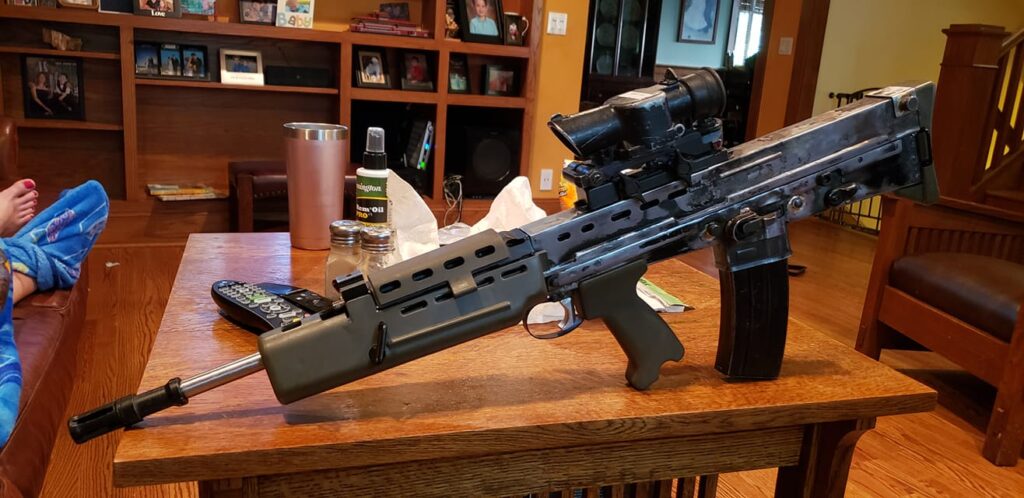
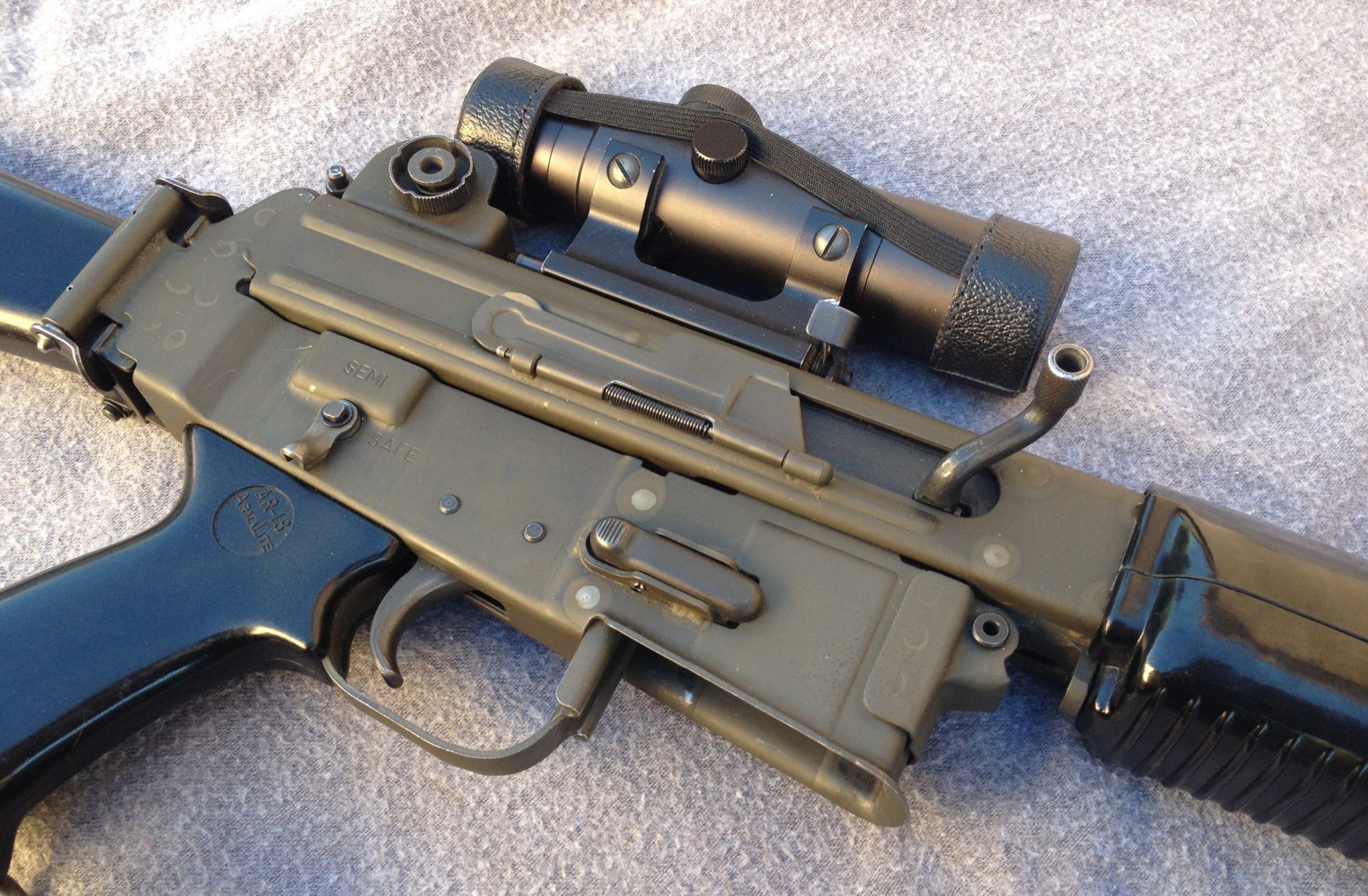
Reader James put together an Airsoft based SA80 and I thought you would like to see some pics of his process. He also wrote me the following in an email which helps explain a lot of the problems I had trying to put mine together.

James wrote quote;

This is a bitch to put together……

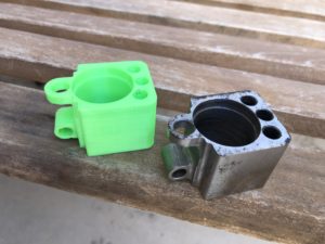
For the upper and the lower. I used a Star Airsoft cause the metal was
a bit thicker then the G&G. They all had issues with spacing.
Basically… Here’s the deal.
You have to use an Airsoft body unless you have a massive press and dies.
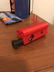
But the airsoft guns all put the magazine too far forward and too far
apart from the trigger pack holes.
The airsoft guns are all too wide by about 2mm. And in some guns like
the G&G, the mag well is too short.
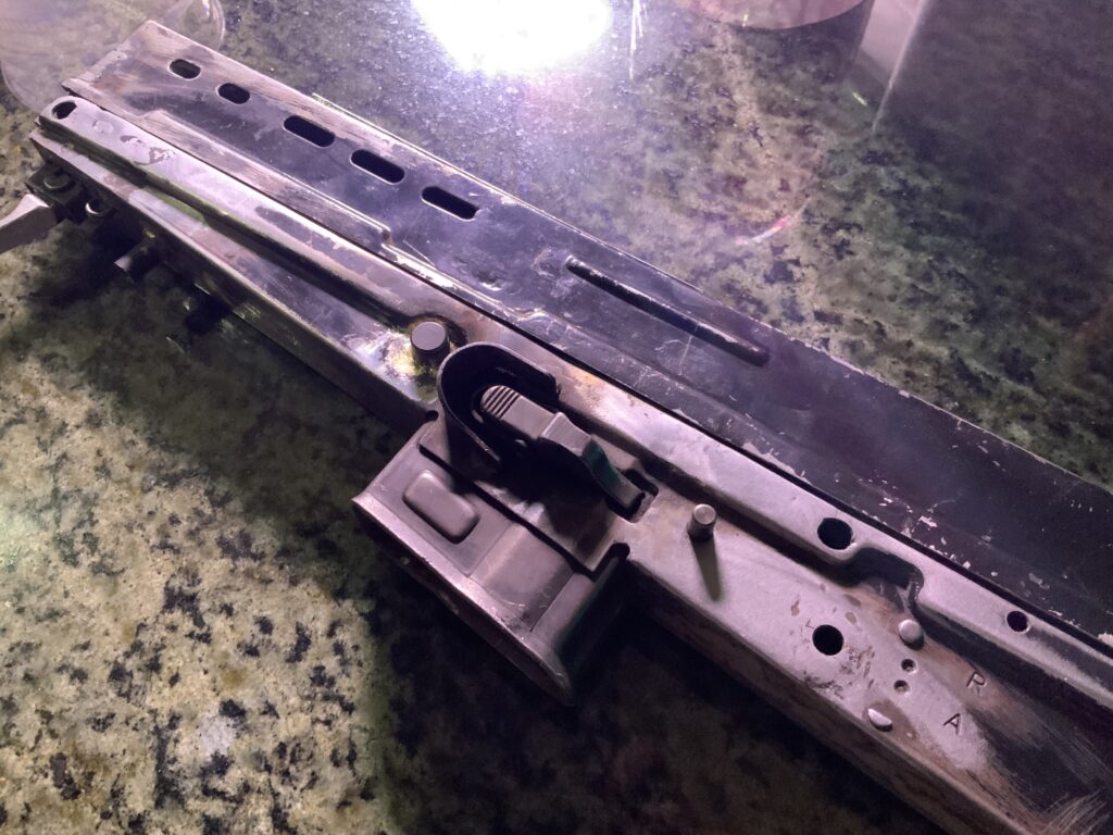
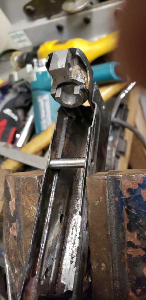
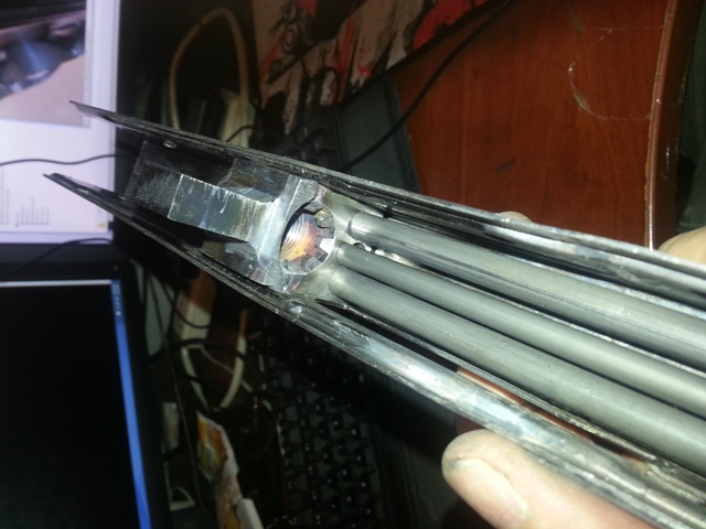
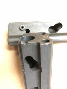
So basically… All uppers and lowers have to quartered and welded back
together. I have some images of how I did this and where I too material
out.
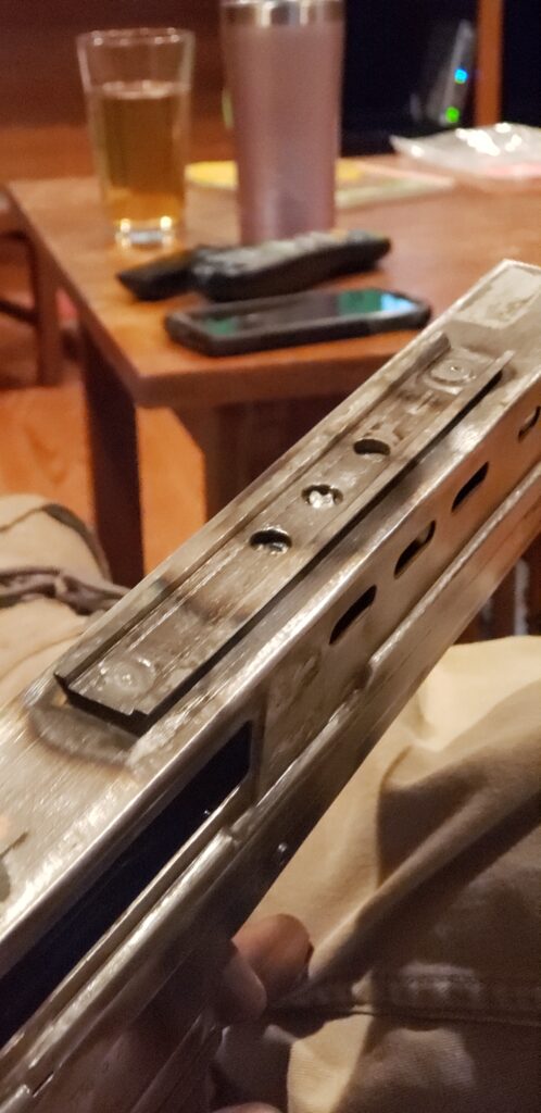
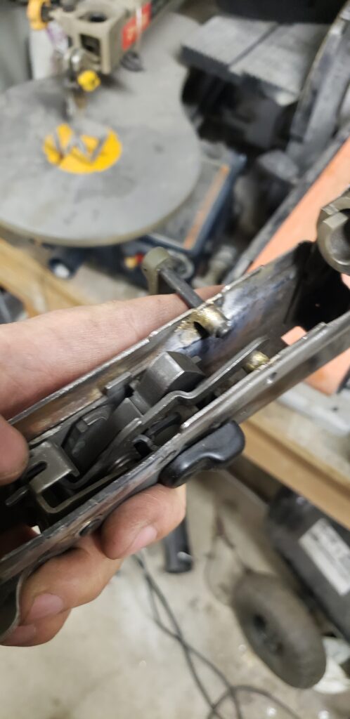
I used the STAR because its was 2mm too long all in the area between the
Magazine and the Trigger pack so I could just take out 2mm right down
the middle, and the mag well accepted AR15 mags without modification.
However, its probably the least like the real steel guns. The G&G and
Army bodies of which I have 2 or 3 each could work, but you’ll need 2
guns to make 1 gun cause the length of the airsoft gun is spot on, but
you need to remove 2mm from the length between the magazine well and the
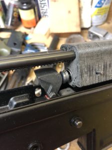
trigger pack. This is all based on were the trigger is and having an
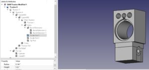
actual trigger rod and a trigger pack. You know the spring guide from
the back of the gun will locate the back of the Barrel extension block
or trunnion. And then the bolt in battery will basically just pass the
Auto sear location.

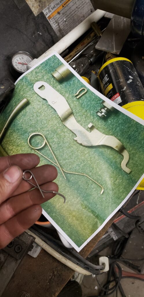
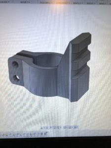
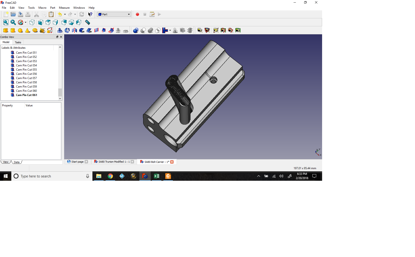
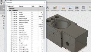
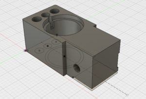
In AutoCAD i made blocks of the pieces that I had for the real gun.
Those I wanted to fit absolutely and I found that those told me where
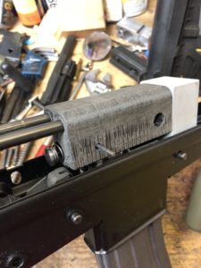
things had to go to make things work. Key points. Spring guide rod.
Trigger Pack holes. Length of bolt hold open level to catch magazine
follower. HK magazine. Auto Sear location on Trigger pack. Auto sear
cam on bottom of bolt. Bolt face with lugs in battery will tell you
where the barrel extension goes.
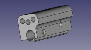
Length of trigger bar from trigger to trigger pack. Those all all
fixed elements which when placed will show you that airsoft bodies need
a shitload of work to make things fit right.

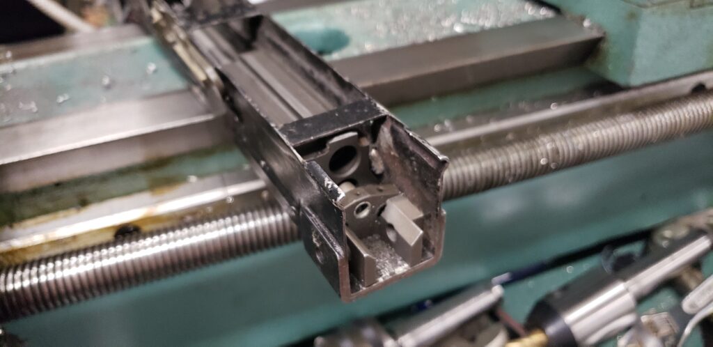
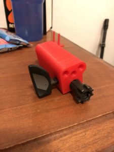
The G&G and Army bodies although they’ll look better need to have 2
airsoft guns each cut into 4 pieces, 1 cross cut and one length wise
cut. Because they don’t have the extra length.

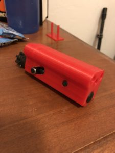
Hope this is helpfull to you.!

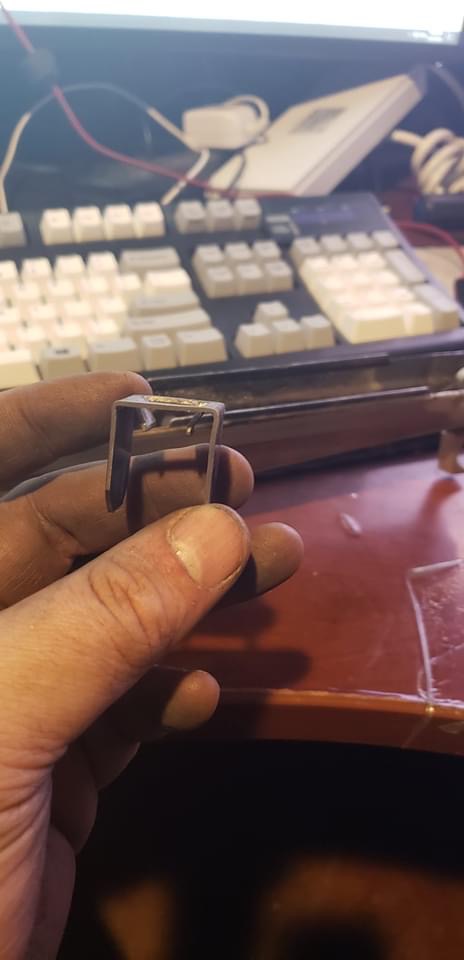
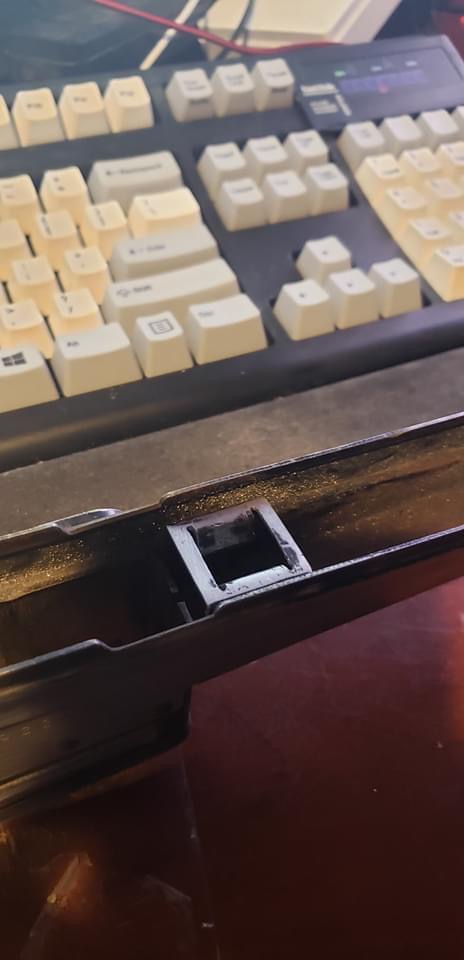
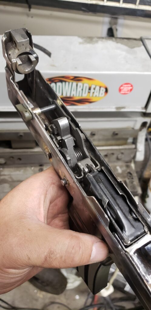
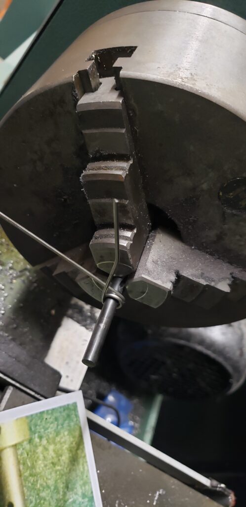
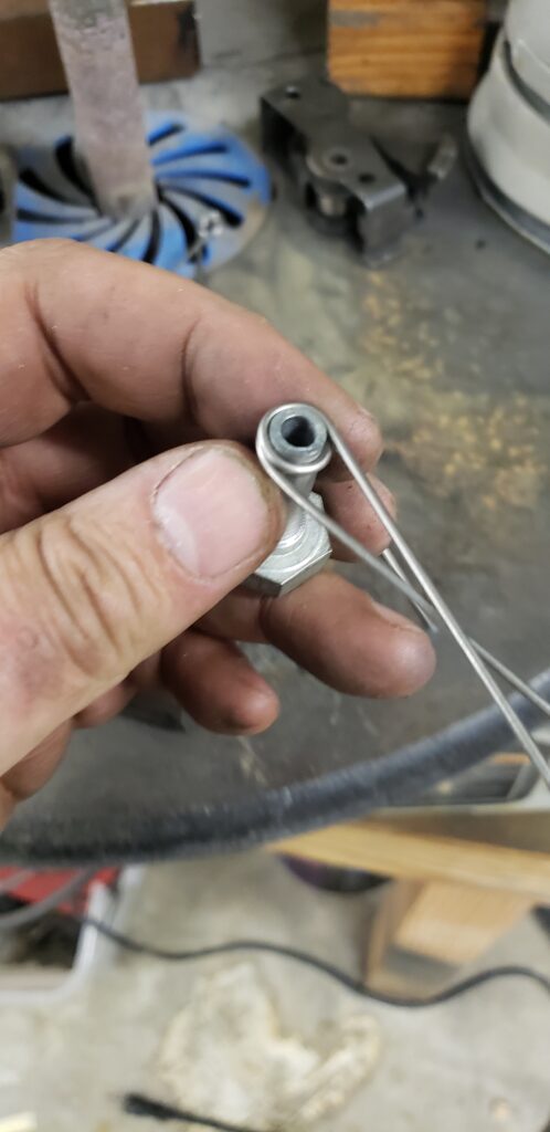
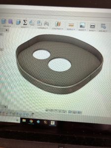
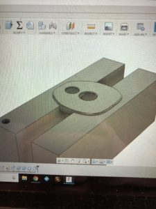
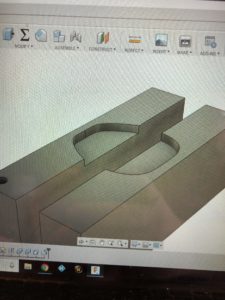
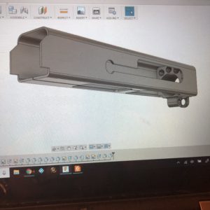
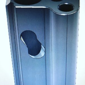
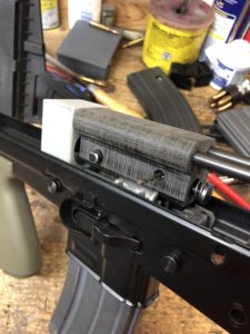
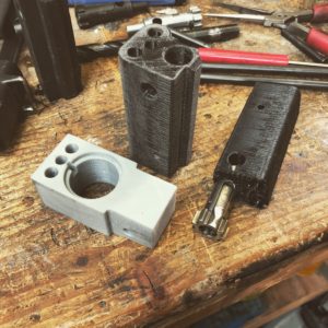
Enjoy the pictures, there are a lot of them!

Project SA80 L85A2: Update

Update

Lots of modeling in Fusion 360 and I got myself a 3D printer and started building my own stuff!

Here is the one I picked up Amazon Click Here

It is the Monoprice Maker Select Plus. I’m loving it.

Some stuff I have been playing with.

AR180C front sight base.


AR180B trunion.

SA80 L85A2 Airsoft bolt carrier

AR180S Hand Guard Retainer and fixture.

AR180B Upper Receiver


Project SA80 L85A2: Bolt Carrier

Project SA80 L85A2

Had my daughter’s friend 3d print me some parts to mock up and it sure is easy to find your mistakes that way.

I have the firing pin retainer hole in the wrong spot as well as the charging handle. The outside dimensions are too big and the bolt carrier rubs on the inside of the upper receiver shell.

The design has been updated and I will get them printed up soon.

I also took the opportunity to model the original bolt carrier that I borrowed.

It is much slimmer than what I was building and it actually will ride on the airsoft guide rails since the holes are larger. This is where the frustrating part starts. When putting the original bolt and carrier in the gun it won’t strip rounds from the magazine. Either the original guide rails are lower in the receiver or the magazine is higher. I’m working on getting some more original parts to try in this shell and see where I am at.

I’m not giving up but I am having that nagging feeling that I might be stuck turning this into a .22LR instead of a 5.56.

Regardless of how it turns out I have learned a lot just from teaching myself Fusion 360 and from the study of these original parts.

Project SA80 L85A2: FreeCAD, Fusion 360, & Parametric Design

FreeCAD, Fusion 360, & Parametric Design

After building my prototype trunion and trial fitting it to the gun I was able to tweak some of the dimensions and put things down on paper so to speak.

As many of you may have noticed from earlier posts, I have been using FreeCAD. It is light weight and runs well on my laptop which allows me to work on my designs on the road.

When drawing up the bolt carrier I ran into a snag. The cam pin slot.

My first attempt was to create multiple cylinders that would approximate the path of an end mill.

I attempted to combine all of these overlapping cylinders into one object then remove it from the bolt carrier. FreeCAD choked, locked up my computer and I lost all my progress. When researching how this type of operation is usually done in CAD I discovered that FreeCAD does not yet allow you to draw a spline on a curved surface and then have a cylinder follow that spline. Whatever that means.

I was chatting with Chuck at GunLab.net and he said he has moved over to Fusion 360 and really likes it. I signed up and discovered that educators like myself (or quite frankly anyone who claims to be a student, educator, or hobbyist) get it for free. That sounds like a bargain to me.

Try it yourself and let me know how you like it. Click Here. 

I started playing around with it and after watching a few videos on youtube I was getting the hang of it and redrawing my trunion design. It was then that I happened across a series of tutorials that really connected with me. One in particular (Click Here) talked about parametric design. It was like a light bulb went off and I realized how this would be the perfect way to do my project as well as any projects down the road. I suggest if you are a complete newb like myself that you watch all his “Learn Fusion 360 or Die Trying” videos.

Parametric design deals with designing and dimensioning based on parameters or variables. Parameters are set up ahead of time and given a dimension. Drawing uses the name of the parameter and not the dimension itself. That doesn’t seam like a big difference but if you have to change a dimension because the part doesn’t fit or you want to modify it after the fact, it makes a world of difference.

FreeCAD requires you to hunt down the actual step you performed in the design tree and if you did not rename them to something descriptive you will have a tough time. In fusion 360 you only have to change the dimension in the parametric table and it updates the entire drawing to reflect that.

This is exactly what I need for this project because after building these two parts I will test fit them and make further refinements to the drawing. It will take seconds to update the drawing.

I built the trunion from the ground up in Fusion 360 and after a couple hiccups I have it ready to build. The bolt carrier that I drew in FreeCAD is good enough for now. I only extruded a hole for the cam pin and this will fix the bolt in the fully extended position. This will allow me to check if rounds will feed and eject. That is the next hurdle and what will require dimension changes in the current design.

In addition to using CAD instead of paper drawings I also am going to 3D print these two parts for the initial trials. Only after I have the design working in plastic will I move ahead with making them in steel. I feel like I have actually moved into the end of the last century with my skills.